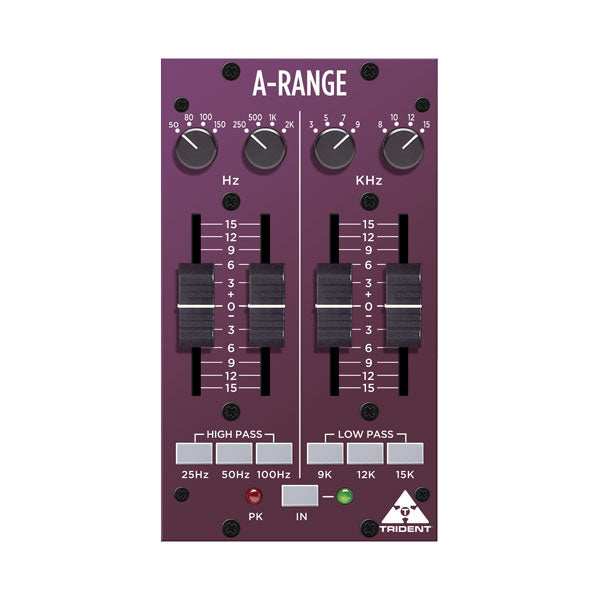
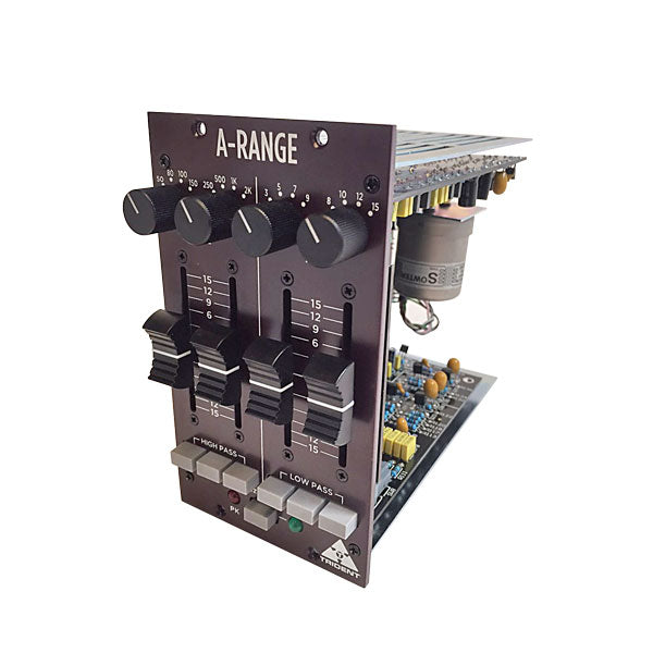
Begin with all boost/cut faders set to their mid way (‘0’) positions. Adjust the low and high mid frequency controls to their minimum positions (fully anticlockwise). The high and low pass filter switches should be in their out positions. Set the frequency select switches controlling the high and low shelving sections, to 150Hz and 12kHz respectively. Lastly,press the ‘IN’ switch (the associated green LED will light).
Pushing up any of the four faders beneath its associated frequency select switch, will result in the chosen frequency being boosted. Moving the faders below centre will result in the chosen frequency being cut. Operating the frequency select switch in the high section (8kHz to 15kHz shelving) will introduce a subtle change of emphasis. Operating the frequency select switch in the upper mid section (3kHz to 9kHz peaking) will introduce a distinct difference according to the frequency selected, since it is now peaking rather than shelving and also due to the characteristics of the inductor-based circuitry. Operating the frequency select switch in the ‘lower mid’ section, 250Hz to 2kHz peaking, will also introduce a distinct difference according to the frequency selected, again because of its peaking nature and the use of inductors in this part of the circuit.
Operating the frequency select switch in the low section, 80Hz to 150Hz shelving, will introduce an effective change of emphasis to the low frequencies.
Finally, the three shelving ‘low-pass’ and ‘high-pass’ filter sections are employed to introduce a roll-off of either high frequencies or low frequencies respectively, according to which of the three push buttons are selected in each section. The high-pass filters are useful for the minimization of extraneous low frequency ‘rumble’ caused, for example, by someone’s feet moving about near a microphone stand, nearby traffic noise, AC systems, etc. Additionally, a high-pass filter can be used effectively during recording to reduce the accumulation of low frequency sounds that can adversely affect a mix. The three high-pass corner frequencies are 25Hz, 50Hz and 100Hz. The low-pass filters are used to minimize high frequency noise that may cause ‘harshness’ in a vocal, or to tame the output of a violin or guitar amplifier, etc. Low-pass filtering is often employed on kick and snare drums and bass guitars, as well as a means of reducing ‘hiss’. The three lowpass filter frequencies on the A-Range® are 9k, 12k and 15k. Filters can also be used in combination for greater effect.
The amount of boost or cut required for any particular programme material is a very subjective matter and is usually found by experiment. Use the ‘IN’ switch to make comparisons between EQ’d and non-EQ’d signals. Keep an eye on the red “PK” LED: occasional flashes are OK but if it is on all the time, turn down the input level to the A-Range® module. using whatever modules precede it in the signal chain.
Extended Function
If you have a Radial Work horse™ or compatible rack, you can send the output of the A-Range® to the rack’s internal mix buss. To do this, locate jumper J1 on the main circuit board near the edge connector. Move the jumper onto the two pins nearest R53.
